Project log: Filament weight display
Published on

The finished project
One problem1 I have when 3D printing is that it’s hard to gauge whether there’s enough filament left on a roll to complete a print. Sometimes it’s obvious when the print is small or the roll is full, but often it’s not. If I’m unsure about it, I end up obsessing over the printer instead of just leaving it to do its thing.
The typical approach to this problem is to use a run-out sensor, which stops the printer when it detects that the filament is no longer running through it. I’d rather know in advance though: it’s no good stopping the print if I’m making something that has to look nice and now half of it is one colour and the remainder will be something else.
While browsing around for ideas, I came across a project that used a load cell to measure the weight of the filament roll2. I didn’t really know what a load cell was, but decided to do some research and see if I could build my own. I didn’t actually read the article I found, intending to figure things out on my own if I could.
Load Cells 101
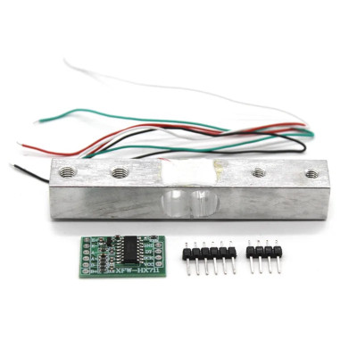
A load cell, its amplifier, and some random headers
At the heart of the project is a load cell. It turns out these are the things that do the lifting in most electronic scales. They’re basically a carefully machined metal bar with a strain gauge attached to it. The strain gauge is a long trace of conductive material that runs back and forth across the middle of the bar. When the bar bends very slightly (due to load), the conductor flexes with it and gets longer or shorter; that flex changes its resistance by a tiny amount, which can be measured using a Wheatstone bridge.
The Wheatstone bridge is a diamond of resistors, and requires an ’excitation’ voltage to be applied across it in one direction, and the resistance is then read from the perpendicular pair. As the resistance is tiny, and the changes even more tiny, you generally need an amplifier to read it and output something more useful. The HX711 is such an amplifier, and is so ubiquitous that most places that sell load cells will just bundle one with it.
The HX711 connects to the load cell using four wires: two for the excitation voltage, and two for the output. On the other end it takes a 5V input, ground, and then has two pins to deal with the onward communication: one for a clock signal, and one for data. We’ll get back to that later!
Early prototyping

The prototype, mid-debugging
I decided early on to base the project around an RP2040-based board, as I had previous experience with them and they’re cheap and easy to get hold of. I started off with a Raspberry Pi Pico, slotted it into a breadboard, and connected it to the HX711. A short search produced three or so different python libraries, but I couldn’t get any of them to work reliably.
If you look at the picture of the prototype, you’ll notice a large bundle of wires to the left. These are connected to a logic analyser I bought to try and understand what on earth was happening, because it seemed like the code should work, and there was definitely some communication with the HX711 happening, but none of the readings made any sense.
At one point I noticed that moving my head near to the Pico caused the readings to change, but I didn’t understand the implication of that3. I went to bed unable to figure out what was going on, and just before I dozed off realised that I must have the pins configured wrong. The next day I checked the spec sheet and discovered that the pin with the number “1” silk-screened next to it is in fact GPIO 0, not GPIO 14. The pin the Pico was trying to read data from wasn’t actually connected to anything, which is why waving my hand near it was enough to induce a signal.
Updating the code to use the correct pins made everything work much better and I started to get sensible readings. At this point I came across the RP2040-Zero by Waveshare, which is not only a smaller, cuter, cheaper Pico, but has silk-screened numbers that actually match the GPIO pin numbers (plus an actual a reset button!). I immediately bought several, and switched the prototype over as soon as they arrived.
The rest of the prototyping was reasonably uneventful. I used a little OLED screen I had sitting around from a past Ali Express order, and once again there were several python libraries to handle it. Soon enough I had raw weight readings from the load cell (which was stuck to my desk with painters’ tape) being displayed on the screen.
The load cells don’t measure absolute weight, so you have to “calibrate” them by remembering the reading when there is no load, and then applying a scaling factor to turn the raw reading into a weight. I worked these out by putting a known weight on the business end of the load cell, and then hard-coding the numbers.
An interruption to deal with interrupts
One thing I noticed with the MicroPython libraries for the HX711 is that they relied on polling the data pin to see if there was any data to read. The way the HX711 communicates is by pulling the data line low when it has data; you then have to pulse the clock line to get it to shift a bit of the reading out over the data line. The HX711 I have operates at 10Hz by default5, and reading the data takes almost no time at all, so the most “efficient” thing to do is to sleep for 100ms between readings.
This is fine if you’re not doing anything else, but gets awkward if you also want to refresh a screen at certain points, or check for button inputs, etc. It also upset me to see the data line being low for so long when viewing the logic analyser traces. The RP2040 supports setting interrupts on the GPIO pins, but I couldn’t find anyone who was actually using them for the HX711.
I therefore did the only sensible thing: wrote my own library, using interrupts to monitor for data availability. It was pretty straightforward, but didn’t actually work consistently. Looking more closely at the other libraries, they all do something to try to increase the speed at which the clock signals are written6: some were disabling interrupts, others were using assembly. I, again, did the only sensible thing: I threw all the python away and wrote a new driver in TinyGo.
My new code is event driven: it adds interrupts for button presses, and one for the HX711 data line. When the data line is pulled low, it removes that interrupt (so it doesn’t fire for every bit of data we receive), does the reading logic, then re-adds the interrupt. Theoretically if you spam buttons at an inopportune time you could mess up a reading, but the reading 100ms after would be fine. So my code spends most of the time idle, which translates to very little power draw.
User experience
While prototyping I was using some standard small push buttons to navigate the user interface I was creating. I soon realised that if I needed to enter weights on the real device I wasn’t going to be happy poking an annoying little button hundreds of times, and I didn’t feel like coding anything more elaborate to make input easier. Instead, I switched to using a rotary encoder. This is a bit like a variable resistor, but it can rotate completely freely, and sends a signal when it’s turned. It also has a button built in, so you can press it down to select things.
It took me a while to get the hang of the rotary encoder: it has two data pins for turning, and you have to wait for a falling edge on one pin and then immediately read the other to figure out which way it’s turning. My initial attempts at doing this weren’t quite immediate enough7, so I ended up with somewhat random data. Trying to select a number when going right sometimes increases it and sometimes decreases it is an exercise in frustration.
The correctly functioning rotary encoder makes it much easier to input numbers and change settings. I ended up with a very simple menu system at the bottom of the screen which lets you cycle between three options: setting the spool weight, zeroing the scale, and calibrating it. Zeroing is the most straightforward option: it simply reads the current value, and saves it as the zero offset in the flash memory. Selecting spool weight enters a mode where turning the rotary encoder increases or decreases the spool weight by a gram at a time; pressing the encoder in saves the value to flash and exits the mode8.
Calibration is a bit more confusing. Changing the spool weight changes the value you see on the screen directly and predictably. Calibration instead affects the “scale” value you can’t actually see; you just see the effect of the scaling on the weight reading. Still, if you have a known weight on the scale you simply rotate the encoder until the right weight is displayed on the screen. Pressing the encoder saves the value to flash as with the other modes.
Putting it together
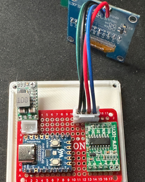
The final assembly
The final step was to assemble everything in a way where it would be usable, and wires wouldn’t keep falling out whenever you looked at it. I found some cute little prototype boards that would just about fit all the components on – I left the OLED screen and rotary encoder off so they could be mounted to the front of the box.
I obviously 3D printed the enclosure, because I own a 3D printer and therefore spend a lot of my time 3D printing parts for my 3D printer. In my first prototype I put raised areas on the back panel and put some heat-press inserts in them, intending to screw down the protoboard. The screw holes I was going to use, however, were underneath the soldered-down RP2040-Zero and HX711. I instead uninserted the inserts and simply put some screws through the back panel with the intention of slotting nuts under the components. This turned out to be both incredibly annoying and entirely unnecessary; the board sits at the back of the box on its own, and there’s no real danger from it having a bit of freedom.
While I was prototyping I was powering the circuit from the USB port on the microcontroller, but for the actual unit I added a buck converter and ran a cable from the 3D printer’s power supply (which outputs 24V). This has the handy side effect of turning the scale on and off with the printer. I’ve recently bought a bench power supply, which made testing this part a lot easier: being able to dial in a voltage and current limit and then just plug things in is great.
The other thing that needed to change between my prototype and the final version was the load cell. It needed to be attached to the printer in such a way that one end bore all the weight of the spool (and, you know, not stuck to my desk with painters’ tape). I was originally going to do something fancy with bearings, but settled on the easier option of a spool holder which uses the same threading as the original, so it slots straight in:
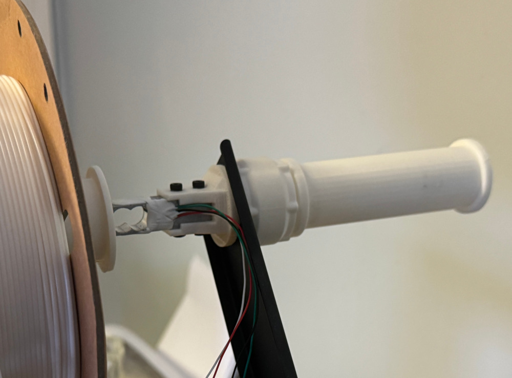
The load cell mounted as part of a spool holder on the printer.
With all of this done, I invented a complicated mounting system to keep it attached to the printer. Any resemblance to blue painters’ tape is entirely coincidental.
Bill of materials and sources
Here are the major components that I ended up using:
| Part | Source | Cost |
|---|---|---|
| RP2040-Zero microcontroller | WaveShare | £3.15 |
| 5KG load cell + HX711 | AliExpress | £1.89 |
| Buck converter | AliExpress | £0.51 |
| SH1106 OLED module | AliExpress | £1.70 |
| Rotary encoder | AliExpress | £0.80 |
| Mini PCB prototype board | Amazon | £1.49 |
Where things come in packs of more than one, I’ve listed the cost of one unit. I’ve not included things like wires, connectors, or the filament used in printing the enclosure as you can use whatever you have to hand.
The source code I wrote is available on GitHub, and the designs for the 3D printed parts are shared in OnShape.
-
Among many, many others, of course. ↩︎
-
I can’t actually find where I saw this original project now, but there are quite a few kicking around if you search. ↩︎
-
This happened at about 1am and I was tired and frustrated. That’s my excuse, anyway. ↩︎
-
At this point I realised I’d made the exact same mistake the last time I used a Pico. Fool me once, etc. ↩︎
-
You can change this to 80Hz by resoldering a resistor on the board, but 10Hz is already several orders of magnitude faster than I actually need. ↩︎
-
If the clock signal stays high for longer than 60ms it’s treated as a shutdown signal by the HX711. This is somewhat unideal when you’re trying to read data from it. ↩︎
-
Because of my very clever interrupt system. I wanted to do as little work in the interrupt handler as possible, so I was just enqueuing an event to be processed in the main loop. This introduced enough delay that I wasn’t reading the second pin at the right time. The solution was to read the pin in the interrupt handler and then just enqueue a “left” or “right” event instead of my original “turning somehow, you figure it out” event. ↩︎
-
I was initially planning on hard-coding the weights for all the spools I’m likely to use, and just having a way to switch between them. But the thought of having to re-flash the device every time I bought a new type of filament made me reconsider. Plus, it was way easier to not do that. ↩︎
Have thoughts that transcend nodding? Send me a message!
Related posts
Adventures in 3D printing
I’d been idly considering getting a 3D printer for a while, but have only recently taken the plunge. I picked up a Sovol SV06 from Amazon for £199.99, which is a model commonly recommended for beginners. About three weeks later, I think I’ve finally finished fixing all the problems the printer has, and thought I’d document them. Setup and out of the box performance The setup of ...
Home Automation Without the Megacorps
I first experimented with home automation in 2016, by picking up a Samsung “SmartThings” hub. It was terrible. The UI to configure things was slow and clunky, firmware updates were applied whether you wanted them or not, and everything stopped working if their cloud services stopped. You were also locked into whatever integrations they deigned to support, of course. After that broke fo...
Further adventures in 3D printing
Not quite a year ago, I bought a Sovol SV06 3D printer and wrote about my initial experiences. At the end I joked:
{% figure "left" "Filament weight display" %} One problem[^1] I have when 3D printing is that it's hard to gauge whether there's enough filament left on a roll to complete a print. Sometimes it's ...